Monitoring Heat Recovery Performance with ESPHome and Home Assistant
In my home, I have a mechanical ventilation system with heat recovery powered by Stiebel Eltron V-400. Basically, it’s a large fan with air inflows and outflows ducts. Besides some built-in automation, it’s a pretty dumb device. Without a dedicated gateway (which costs extra money), I can only control it or see its current parameters on the controller, either on the unit or in the hall.
I thought it would be nice to collect some data from this device, both for some kind of analysis and out of curiosity. I run Home Assistant, which can display dedicated graphs and dashboards for such purpose. And, because I recently played with ESP boards, the idea was born pretty quickly.
Parts
For this project I used Dallas DS18B20 temperature sensors and a Wemos D1 with ESP8266 onboard. I picked the Wemos D1 because of 5V output, compact size, and because I had a one spare at this moment.
The Dallas DS18B20 is well-known for its 1-wire protocol, which allows you to connect multiple temperature sensors to a single data line. If you’ve ever wondered about the project where you can use more than one DS18B20 temperature sensor on a single board – here’s one.
I also had a 6-pin LED wire, which I split and used to connect the sensors to the board. For power, I used an old phone charger and a USB-C cable.

Plan
The heat recovery unit has four air pipes – two pairs of inflows and outflows. One pair handles air exchange with the outside, while the other circulates air within the house. The airflow setup is as follows:
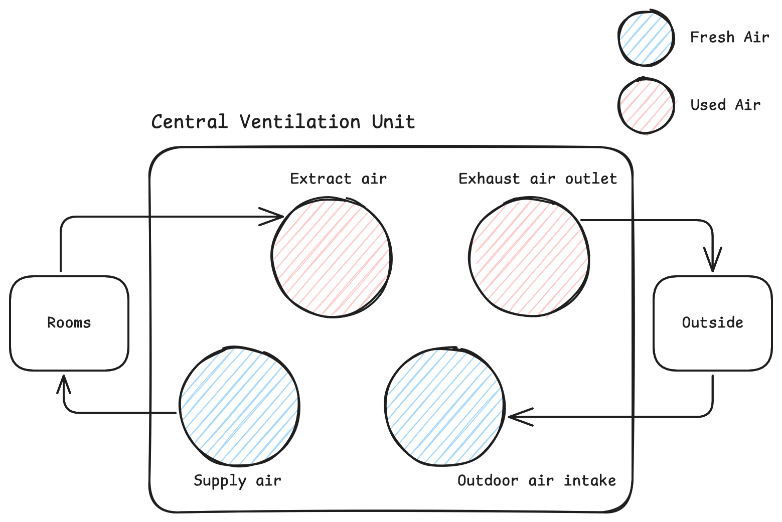
I expected these four pipes would carry air at different temperatures. Inside each one, I placed a single DS18B20 sensor. I added an extra one to measure the temperature in the attic, where the ventilation unit is installed.
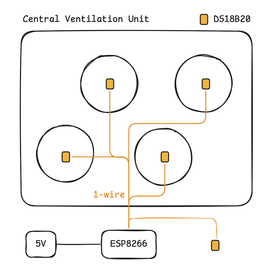
As I mentioned earlier, the DS18B20 uses 1-wire interface, so all sensors can share the same data line. Instead of wiring sensors one into another in a form of chain, I connected them in a star topology, where each sensor has its own dedicated wires, but shares a common data pin.
Preparation
First – the sensors. Soldering the first one was fun, but each subsequent one became a bit more tedious. I soldered each sensor to a wire strip about half a meter long.


I wanted to connect everything on the breadboard. Unfortunately, I realised I was still missing the Dupont crimper needed to prepare proper pins for the sensor wires. I ended up using Wago connectors to make all connections.
I connected the data line to pin D13 (GPIO13) on the Wemos D1.

Firmware
I didn’t write the ESP firmware myself. Instead, I decided to use ESPHome which works seamlessly with Home Assistant.
Setting up the ESP with ESPHome was one of the most magical experiences I’ve had. Even though I enjoy digging into programming and writing things from scratch, being able to generate firmware from a YAML file is just wonderful.
Identifying sensors
I started with a basic ESPHome project, configured WiFi connection and set up the one_wire protocol.
one_wire:
  - platform: gpio
    pin: GPIO13
Then, after flashing the firmware, ESP printed the addresses of the connected sensors
[13:47:40][C][gpio.one_wire:021]:   Pin: GPIO13
[13:47:40][C][gpio.one_wire:080]:   Found devices:
[13:47:40][C][gpio.one_wire:082]:     0x48e2a7bc12fa3651 (DS18B20)
[13:47:40][C][gpio.one_wire:082]:     0xc903deab6719b425 (DS18B20)
[13:47:40][C][gpio.one_wire:082]:     0x1f64b28d4ca713ff (DS18B20)
[13:47:40][C][gpio.one_wire:082]:     0xa82fbac2e19d54e7 (DS18B20)
[13:47:40][C][gpio.one_wire:082]:     0x702c19f8ab65e038 (DS18B20)
All of my sensors were visible, but there was one problem. I wanted to name each sensor correctly, but I didn’t know which address was assigned to each one. Fortunately, the sensors are very sensitive and I just registered all of them, assigning the names. Then, I warmed up a specific one and observed which temperature reading increased.
That could have been enough, but I decided to use the different colored wires for inner flow and outer flow temperatures, so I needed to update the names accordingly. I ended up with the list as follows.
sensor:
  - platform: dallas_temp
    id: temp_inner_inflow
    address: 0x48e2a7bc12fa3651
    name: temp_inner_inflow
    update_interval: 60s
  - platform: dallas_temp
    id: temp_inner_outflow
    address: 0xc903deab6719b425
    name: temp_inner_outflow
    update_interval: 60s
  - platform: dallas_temp
    id: temp_outer_inflow
    address: 0x1f64b28d4ca713ff
    name: temp_outer_inflow
    update_interval: 60s
  - platform: dallas_temp
    address: 0xa82fbac2e19d54e7
    name: temp_attic
    update_interval: 60s
  - platform: dallas_temp
    address: 0x702c19f8ab65e038
    name: temp_outer_outflow
    update_interval: 60s
Temperature efficiency
With all those temperatures available, I configured another sensor to calculate the temperature efficiency of the heat exchanger.
The formula is
$$ \eta = \frac{T_2 - T_1}{T_3 - T_1} \times 100%$ $$
- $T_1$ – outdoor temperature before heat exchanger
- $T_2$ – temperature of supply air after heat exchanger
- $T_3$ – temperature of extracted air from rooms
The ESPHome definition:
sensor:
  - platform: template
    name: efficiency
    filters:
      - round: 2
    unit_of_measurement: '%'
    state_class: "measurement"
    accuracy_decimals: 1
    lambda: |-
      float t1 = id(temp_outer_inflow).state;
      float t2 = id(temp_inner_inflow).state;
      float t3 = id(temp_inner_outflow).state;
      float eff = (t2 - t1) / (t3 - t1);
      return eff * 100;
    update_interval: 60s
I could have done the same using a Home Assistant template sensor. However, doing it directly on the ESP allowed me to offload some work from the main instance and bring the calculation closer to the data source. The data is already available to the ESP, so it can expose the pre-calculated value as part of its API.
Deployment
The initial deployment was a bit different from a traditional software development workflow. I had to visit my attic, gently place all the sensors inside the air pipes according to the plan, and power up the Wemos D1 board.
Once everything was in place, I switched over to Home Assistant.
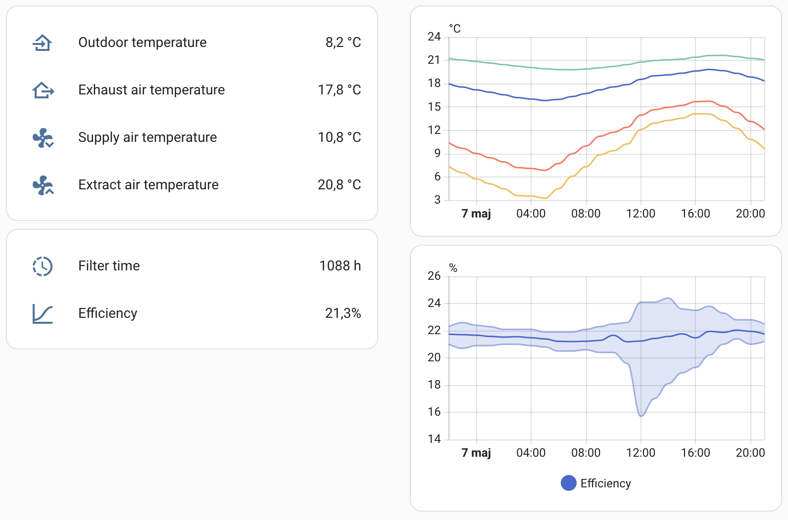
Home Assistant dashboard
Since I already had ESPHome integrated with Home Assistant, the new device was automatically discovered and all exposed entities were registered. I tweaked the names and prepared a dashboard to have a quick overview of my ventilation unit.
I’m not going to show you step-by-step configuration here, but if you think it would be useful for you, just drop me a message. I’ll be happy to share the details.
Final thoughts
This setup is working flawlessly for half a year. In the next iteration, I’m going to give the ESP a dedicated case and replace the Wago connector. But once it’s working, the urge to improve it is lower than I expected.
I hope you found this write-up useful. Thanks for reading!
Enjoyed this post?